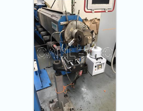
Application
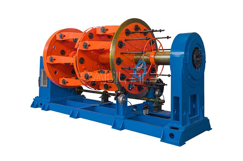
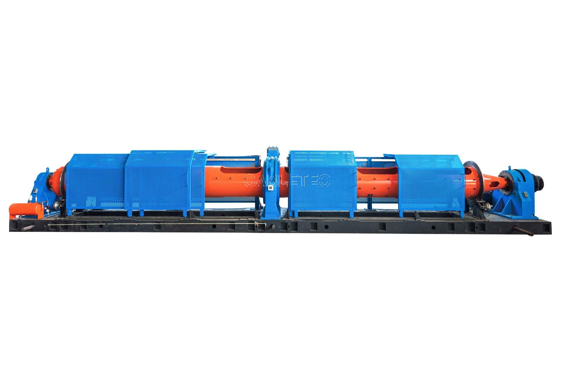
Our product are widely used in wire, steel wire, electrical wire, cable, textile industry etc. It is used for traversing and winding of wire, cable and heavy rope onto bobbins, spools and reels.
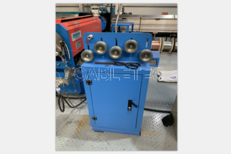
Product feature
Stepless speed regulation: no need to change the rotation speed of the polished rod, as long as to adjust the handle position on the dial, you can freely adjust the speed of the reciprocating motion of the device on the polished shaft, to accurately adjust the needs of the traversing pitch.
Instantaneous commutation: it is not necessary to change the rotation direction of the polished rod. When the commutation arm impactor hits the commutation block, the traversing unit will immediately go in the opposite direction.
Release function: there is no need to stop polished rod, you only need to release the handle according to the arrow pointing to rotate 90 °. The traverse unit can stop moving automatically, and use hands to move it freely on the polished rod.
High speed winding displacement: the maximum rotation speed of the polished rod is about 1000 RPM, which can meet the requirements of high-speed wiring and frequent commutation.
Installation and commissioning
Polished shaft: In order to prevent the polished shaft from being blocked by the dust-proof sheath at both ends of the box, the sheath hole should be adjusted first, then the release handle should be placed in the relaxed position, and then the polished shaft can be rotated into several bearing holes in the box. The release handle is then pulled to the working position.
Determining the rotating direction: Facing the dial, the front of the polished shaft upward rotating is called forward rotation, and the wheel of the reversing arm should face the side of the scale. The front of the polished shaft upward rotating is called reverse rotation, the wheel of the reversing arm should be turned to the back of the traversing box; otherwise the traversing unit can not be reversed. When the product leaves the factory, it is usually assembled by the forward rotation of the polished shaft.
Polished shaft rotating speed: The take-up bobbin rotating speed should be higher than the polished shaft rotating speed. The speed ratio can be selected between 5:1 and 1:1, the speed ratio is larger when the wire diameter is smaller, and the speed ratio is smaller when the wire diameter is larger.
Traversing path: Adjust the position of the two reversing stops on the screw rod so that the length of the reciprocating path matches the position and length of the take-up bobbin.
Maintenance
Maintenance: Work environment should be dust-proof. No. 20 mechanical oil is coated on the polished rod to keep the oil film, and oil protection is applied to the rotating part of the reversing spring
Commutation failure: When the commutation is too slow or not, check whether the rotation is blocked by hand to remove it. If the spring has insufficient elasticity, the spring can be replaced and the support points of the spring can be lubricated
Insufficient thrust: The screw plugs on the top, middle and bottom sides of the box can be tightened clockwise. It is advisable to satisfy the thruster of alignment. Too tight adjustment of the screw plug often leads to poor commutation and reduces the service life of the wire arranger.
Uneven wiring arrangement: the eccentric sleeve on the back of the box should be adjusted. Eccentric sleeve usually has top wire locking, should first loosen the top wire for fine-tuning; when the left and right travel pitches reach the same, tighten the top wire again.
Graphical representation and parameter

Type | ZK(Recommend) | d | d1 | d2 | L1 | L2 | L3 | L4 | L5 | L6 |
PX15 | 400 | φ15 | φ12 | φ12 | 66 | 40 | 30 | 5 | 5 | 9 |
PX20 | 450 | φ20 | φ16 | φ17 | 68 | 40 | 30 | 5 | 5 | 14 |
PX30 | 600 | φ30 | φ20 | φ24 | 72 | 40 | 28 | 6 | 6 | 16.5 |
PX40 | 700 | φ40 | φ28 | φ29 | 80 | 45 | 28 | 7.5 | 8 | 24 |
PX50 | 900 | φ50 | φ32 | φ34 | 82 | 45 | 28 | 7.5 | 10 | 28 |
PX60 | 1200 | φ60 | φ38 | φ39 | 84 | 45 | 28 | 7.5 | 10 | 33 |

Type | S | T | U | V | W | d | X | Y | Z1 | Z2 |
PX15 | 28 | 110 | 72 | 58 | 80 | φ32 | 30 | 14 | M8 | 2-M8 |
PX20 | 38 | 130 | 91 | 68 | 93 | φ40 | 40 | 16 | M10 | 2-M8 |
PX30 | 48 | 150 | 113 | 78 | 105 | φ52 | 60 | 20 |
| 2-M10 |
PX40 | 58 | 170 | 136 | 92 | 120 | φ62 | 80 | 22 |
| 2-M12 |
PX50 | 68 | 190 | 170 | 111 | 140 | φ72 | 110 | 24 |
| 2-M14 |
PX60 | 78 | 210 | 198 | 122 | 152 | φ80 | 120 | 26 |
| 2-M16 |


Type | A | B | C | D | E | F | P | Q | H | K | L | M | N | Thrust (N) | Pitch (mm) |
PX15 | 92 | 56 | 70 | 30 | 8 | 16 | 7 | Φ22 | 51 | 31 |
|
|
| 100 | 0-11 |
4JPX15 | 116 | 56 | 70 | 30 | 8 | 16 | 7 | Φ22 | 51 | 31 |
|
|
| 200 | 0-11 |
PX20 | 111 | 68 | 85 | 40 | 11.5 | 18 | 7 | Φ22 | 60 | 36 | 45 | 200 | 160 | 160 | 0-16 |
4JPX20 | 132 | 68 | 85 | 40 | 11.5 | 18 | 7 | Φ22 | 60 | 36 | 45 | 200 | 160 | 320 | 0-16 |
PX30 | 130 | 85 | 105 | 50 | 14 | 20 | 8 | Φ26 | 70 | 36 | 46 | 200 | 160 | 260 | 0-25 |
4JPX30 | 180 | 85 | 105 | 50 | 14 | 20 | 8 | Φ26 | 70 | 36 | 46 | 200 | 160 | 520 | 0-25 |
PX40 | 160 | 101 | 129 | 60 | 15 | 22 | 8 | Φ28 | 83 | 40 | 50 | 260 | 210 | 420 | 0.5-3.2 |
PX50 | 186 | 119 | 149 | 70 | 19 | 25 | 9 | Φ32 | 102 | 40 | 54 | 400 | 350 | 700 | 1-40 |
PX60 | 238 | 150 | 180 | 80 | 24 | 28 | 10 | Φ35 | 112 | 40 | 60 | 460 | 400 | 1000 | 1.5-48 |